DFF and Gates
📌 Introduction
In this exercise, I explore how D flip-flops interact with basic gates and multiplexers to form sequential circuits.
🧑💻 Code Example
DFF + Gate
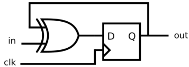
module top_module (
    input clk,
    input in,
    output reg out);

    always @(posedge clk) begin
       out <= out ^ in;
    end
endmodule
Mux and DFF
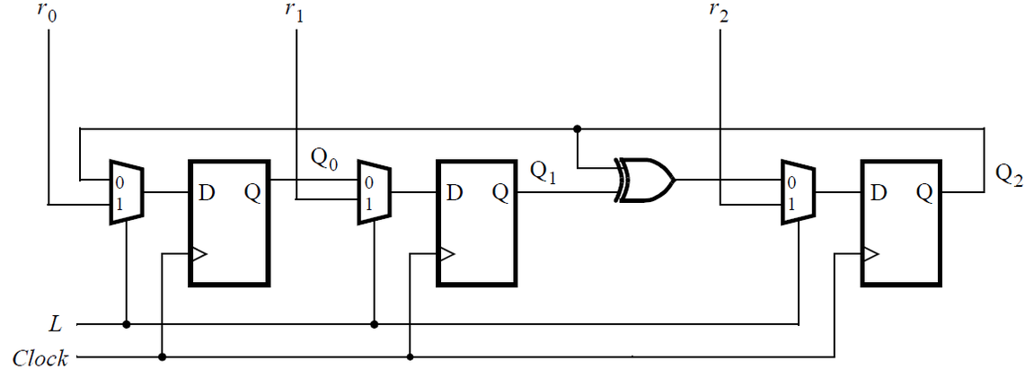
Implement hierarchical Verilog code for this circuit, using three instantiations of a submodule that has a flip-flop and multiplexer in it. Write a Verilog module (containing one flip-flop and multiplexer) named top_module for this submodule.
module top_module (
	input clk,
	input L,
	input r_in,
	input q_in,
	output reg Q);

    always @ (posedge clk) begin
        Q <= (L)? r_in : q_in;
    end

endmodule
Mux and DFF (2)

module top_module (
    input clk,
    input w, R, E, L,
    output reg Q
);

    always @ (posedge clk) begin
        Q <= (L)? R : ((E)? w : Q);
    end

endmodule
DFFs and Gates
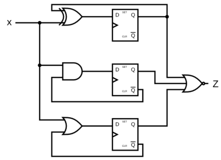
Given the finite state machine circuit as shown, assume that the D flip-flops are initially reset to zero before the machine begins. Be careful with the reset state. Ensure that each D flip-flop’s Q output is really the inverse of its Q output, even before the first clock edge of the simulation.
module DFF_s(input clk, input D, output reg Q);
    initial Q=1'b0;
    always @ (posedge clk) begin
            Q <= D;
    end
endmodule

module top_module (
    input clk,
    input x,
    output z
);
    wire Q0, Q1, Q2;
    //wire Q0_bar = ~Q0;
    wire Q1_bar = ~Q1;
    wire Q2_bar = ~Q2;
    DFF_s dff0(.clk(clk), .D( Q0 ^ x), .Q(Q0));
    DFF_s dff1(.clk(clk), .D( Q1_bar & x), .Q(Q1));
    DFF_s dff2(.clk(clk), .D( Q2_bar | x), .Q(Q2));
    assign z = ~(Q0 | Q1 | Q2);
endmodule