5-bit LFSR (HDLBits)
Galois Linear Feedback Shift Register
📌 Question
A linear feedback shift register is a shift register usually with a few XOR gates to produce the next state of the shift register. A Galois LFSR is one particular arrangement where bit positions with a “tap” are XORed with the output bit to produce its next value, while bit positions without a tap shift. If the taps positions are carefully chosen, the LFSR can be made to be “maximum-length”. A maximum-length LFSR of n bits cycles through 2n-1 states before repeating (the all-zero state is never reached).
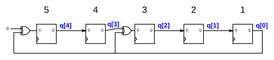
The following diagram shows a 5-bit maximal-length Galois LFSR with taps at bit positions 5 and 3. (Tap positions are usually numbered starting from 1). Note that I drew the XOR gate at position 5 for consistency, but one of the XOR gate inputs is 0.
Hint
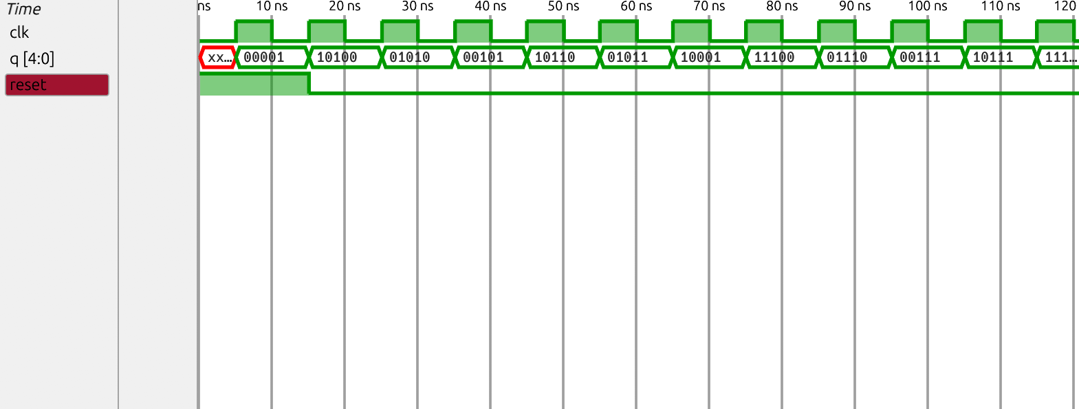
The first few states starting at 1 are 00001, 10100, 01010, 00101, ... The LFSR should cycle through 31 states before returning to 00001.
🧑💻 Code Example
RTL
module top_module(
    input wire clk,
    input wire reset,    // Active-high synchronous reset to 5'h1
    output reg [4:0] q
  );

  always@(posedge clk) begin
    if (reset)
        q <= 5'h1;
    else
        q <= { (q[0]^1'b0), q[4], (q[3]^q[0]), q[2:1] };
  end

endmodule
Testbench
`timescale 1ns/1ps

module tb_top_module;

    reg clk;
    reg reset;
    wire [4:0] q;

    top_module dut (
        .clk(clk),
        .reset(reset),
        .q(q)
    );

    initial clk = 0;
    always #5 clk = ~clk;

    initial begin
        reset = 1;
        #15;
        reset = 0;

        #400;

        reset = 1;
        #20;
        reset = 0;

        #50;
        $display("Simulation Finished");
        $finish;
    end

    initial begin
        $display("Time\t Reset\t q (Hex)\t q (Bin)");
        $monitor("%t\t %b\t %h\t\t %b", $time, reset, q, q);
    end

    initial begin
        $dumpfile("tb_top_module.vcd");
        $dumpvars(0, tb_top_module);
    end

endmodule
Waveform
RTL Schematic

Gate-level Schematic

🔬 Results
