Detect an Edge
📌 Introduction
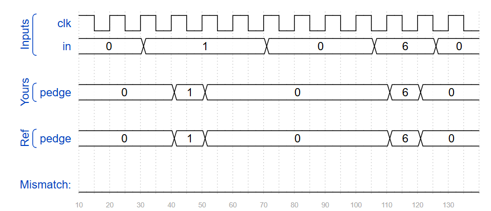
- Detect 0 → 1 transition (positive edge) for each bit in an 8-bit input.
- Store both current and previous states of the signal.
- Output
pedgegoes high for one clock cycle after a rising edge. - Two implementation styles:
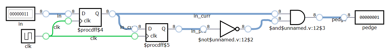
- Two flip-flop version → clearer signal flow (separate current/previous).
- One flip-flop version → more compact (update and detect in one always block).
- Formula:
pedge = current & ~previous - Usage:
- Detecting push-button press
- Event trigger or interrupt edge
- Synchronizing asynchronous signals
🧑💻 Code Example
For each bit in an 8-bit vector, detect when the input signal changes from 0 in one clock cycle to 1 the next (similar to positive edge detection). The output bit should be set the cycle after a 0 to 1 transition occurs.
Two flip-flop version
module top_module (
    input clk,
    input [7:0] in,
    output [7:0] pedge
);
    reg [7:0] in_curr, in_pre;
    always @ (posedge clk) begin
        in_pre <= in_curr;
        in_curr <= in;
    end

    assign pedge = in_curr & ~in_pre;

endmodule
One flip-flop version
module top_module (
    input clk,
    input [7:0] in,
    output reg [7:0] pedge
);
    reg [7:0] pre;
    always @ (posedge clk) begin
        pedge <= in & ~pre;
        pre <= in;
    end

endmodule
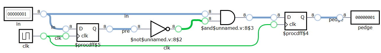
🧩 DigitalJS Note
- The diagram is generated by DigitalJS, which visualizes the RTL structure after synthesis by Yosys.
- Although this version of code looks like “one flip-flop”, the synthesized circuit still has two DFFs:
- One for storing
pre(previous input) - One for storing
pedge(edge pulse output)
- One for storing
- This is correct behavior — both signals need to be held across clock cycles.
- DigitalJS shows RTL-level connections, not real gate-level or timing-optimized results.
- In real FPGA/ASIC synthesis (e.g., Quartus, Vivado), the same two flip-flops will appear.