Universal Shift Register (HDLBits)
Three State Universal Shift Register
📌 題目
Consider the n-bit shift register circuit shown below:
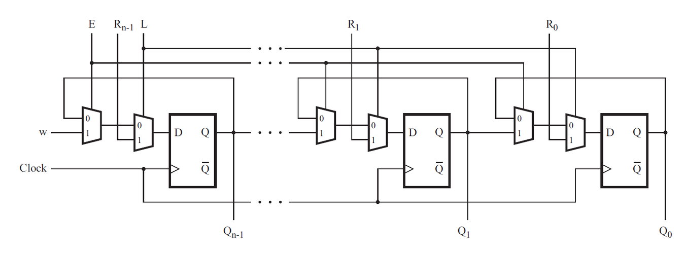
Write a top-level Verilog module (named top_module) for the shift register, assuming that n = 4. Instantiate four copies of your MUXDFF subcircuit in your top-level module. Assume that you are going to implement the circuit on the DE2 board.
- Connect the R inputs to the SW switches,
- clk to KEY[0],
- E to KEY[1],
- L to KEY[2], and
- w to KEY[3].
- Connect the outputs to the red lights LEDR[3:0].
(Reuse your MUXDFF from exams/2014_q4a.) (My Blog Answer: DFF and Gates)
Universal Shift Register
此 Shift Register 可視作一個簡化版的 Universal Shift Register. 結合了 並列載入 (Parallel Load), 右移, 保持資料 (Hold) 功能。
| 操作模式 (Mode) | Load (L) | Enable (E) | 下一個狀態 ($Q_{next}$) | 說明 (Description) |
|---|---|---|---|---|
| Parallel Load | 1 | X | SW[i] |
最高優先權。同步將外部並行輸入載入暫存器。 |
| Shift Right | 0 | 1 | w (i.e., LEDR[i+1]) |
執行移位操作。資料由 KEY[3] 進入,向低位元移動。 |
| Hold | 0 | 0 | Q (自身) |
保持目前狀態不變,不進行載入或移位。 |
這種由 MUX 與 DFF 組成的結構,在積體電路測試(Design for Test)中即為 Scan Cell 的基本雛形。
🧑💻 範例程式
RTL Code
module top_module #(
    parameter WIDTH = 4
) (
    input [3:0] SW,
    input [3:0] KEY,
    output [3:0] LEDR
);
    genvar i;
    generate
        for (i=0; i<WIDTH; i=i+1) begin: Exams_2014q4
            MUXDFF md(.clk(KEY[0]), .w((i == WIDTH-1 ) ? KEY[3] : LEDR[i+1]), .R(SW[i]), .E(KEY[1]), .L(KEY[2]), .Q(LEDR[i]));
        end
    endgenerate

endmodule

module MUXDFF (
    input clk,
    input w, R, E, L,
    output reg Q
);

    always @ (posedge clk) begin
        Q <= (L)? R : ((E)? w : Q);
    end

endmodule
Testbench Code
`timescale 1ns/1ps

module tb_top_module;

    // Inputs
    reg [3:0] SW;
    reg [3:0] KEY; // KEY[0]: clk, KEY[1]: E, KEY[2]: L, KEY[3]: w

    // Outputs
    wire [3:0] LEDR;

    // Instantiate the Unit Under Test (UUT)
    top_module dut (
        .SW(SW),
        .KEY(KEY),
        .LEDR(LEDR)
    );

    // Clock generation (KEY[0])
    initial begin
        KEY[0] = 0;
        forever #5 KEY[0] = ~KEY[0]; // 10ns period
    end

    initial begin
        $dumpfile("tb_top_module.vcd");
        $dumpvars(0, tb_top_module);

        // Initialize Inputs
        SW = 0;
        KEY[3:1] = 0; // Clear control signals (w, L, E)

        // Wait for global reset or startup
        #20;

        // Test Case 1: Load (L=1)
        $display("Test Case 1: Parallel Load SW = 4'b1011");
        SW = 4'b1011;
        KEY[2] = 1; // L = 1 (Load)
        KEY[1] = 0; // E = 0
        KEY[3] = 0; // w = 0 (don't care)
        #10; // Wait for clock edge

        if (LEDR !== 4'b1011) $display("Error: Load failed. Expected 1011, got %b", LEDR);
        else $display("Pass: Loaded %b", LEDR);

        // Test Case 2: Hold (L=0, E=0)
        $display("Test Case 2: Hold value");
        KEY[2] = 0; // L = 0
        KEY[1] = 0; // E = 0
        SW = 4'b0000; // Change SW to ensure we are not loading
        #10;

        if (LEDR !== 4'b1011) $display("Error: Hold failed. Expected 1011, got %b", LEDR);
        else $display("Pass: Held value %b", LEDR);

        // Test Case 3: Shift Right with w=0 (E=1)
        $display("Test Case 3: Shift Right (input 0)");
        KEY[2] = 0; // L = 0
        KEY[1] = 1; // E = 1 (Shift)
        KEY[3] = 0; // w = 0

        #10; // Shift 1: 0101
        if (LEDR !== 4'b0101) $display("Error: Shift 1 failed. Expected 0101, got %b", LEDR);
        else $display("Pass: Shifted to %b", LEDR);

        #10; // Shift 2: 0010
        if (LEDR !== 4'b0010) $display("Error: Shift 2 failed. Expected 0010, got %b", LEDR);
        else $display("Pass: Shifted to %b", LEDR);

        // Test Case 4: Shift Right with w=1
        $display("Test Case 4: Shift Right (input 1)");
        KEY[3] = 1; // w = 1

        #10; // Shift 3: 1001
        if (LEDR !== 4'b1001) $display("Error: Shift 3 failed. Expected 1001, got %b", LEDR);
        else $display("Pass: Shifted to %b", LEDR);

        #10; // Shift 4: 1100
        if (LEDR !== 4'b1100) $display("Error: Shift 4 failed. Expected 1100, got %b", LEDR);
        else $display("Pass: Shifted to %b", LEDR);

        #20;
        $finish;
    end

endmodule
🔬 實驗結果
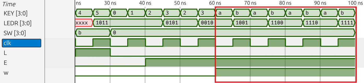
Simulation Waveform
-
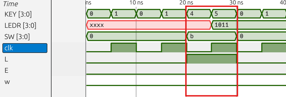
Test Case 1: Load (L=1)
當 L=1, E=0, w=0 時,執行 Load data,而此時 SW 送入的是
4'b1011,因此可以看到LEDR = 4'b1011.
-
Test Case 2: Hold (L=0, E=0)
當 L=0, E=0, w=0 時,執行 Hold,所以可以看到
LEDR仍是4'b1011.
-
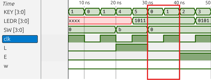
Test Case 3: Shift Right with w=0 (E=1)
當 L=0, E=1, w=0 時,將現有值向右傳且不會 Rotate,LSB 直接向右直接捨棄。
-
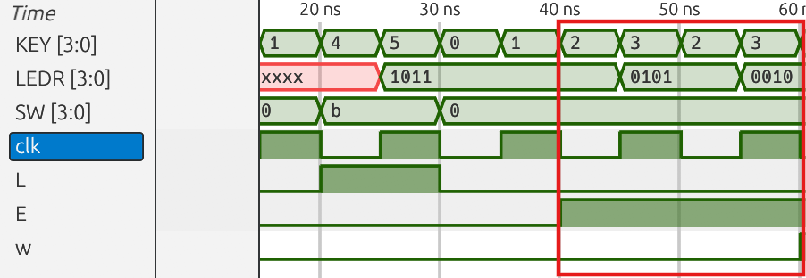
Test Case 4: Shift Right with w=1
當 L=0, E=1, w=1 時,將現有值向右傳且 MSB 傳入 w=1。
Synthesis RTL-level Schematic
