Rule 110 (HDLBits)
Rule 110 Cellular Automaton System (512 Cells)
📌 Question
Rule 110 is a one-dimensional cellular automaton with interesting properties (such as being Turing-complete).
There is a one-dimensional array of cells (on or off). At each time step, the state of each cell changes. In Rule 110, the next state of each cell depends only on itself and its two neighbours, according to the following table:
| Left | Center | Right | Center’s next state |
|---|---|---|---|
| 1 | 1 | 1 | 0 |
| 1 | 1 | 0 | 1 |
| 1 | 0 | 1 | 1 |
| 1 | 0 | 0 | 0 |
| 0 | 1 | 1 | 1 |
| 0 | 1 | 0 | 1 |
| 0 | 0 | 1 | 1 |
| 0 | 0 | 0 | 0 |
(The name “Rule 110” comes from reading the “next state” column: 01101110 is decimal 110.)
In this circuit, create a 512-cell system (q[511:0]), and advance by one time step each clock cycle. The load input indicates the state of the system should be loaded with data[511:0]. Assume the boundaries (q[-1] and q[512]) are both zero (off).
Hint
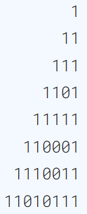
For an initial state of q[511:0] = 1, the first few iterations are:
🧑💻 Code Example
You can also view my Github repo to see the whole project files, include below source code.
Brandon-git-hub/Open_EDA_Example - Rule 110 (HDLBits)
RTL Code
module top_module(
    input wire clk,
    input wire load,
    input wire [511:0] data,
    output reg [511:0] q );

wire [511:0] next_q;
genvar i;

generate
    for (i=0; i <512; i=i+1) begin: Rule_110_generator
        wire left_bit  = (i == 511) ? 1'b0 : q[i+1];
        wire right_bit = (i == 0)   ? 1'b0 : q[i-1];
        Rule_110 circuit(.left(left_bit), .center(q[i]), .right(right_bit), .next_state(next_q[i]));
    end
endgenerate

always @(posedge clk) begin
    q <= (load) ? data : next_q;
end

endmodule

module Rule_110 (
    input wire left,
    input wire center,
    input wire right,
    output reg next_state
);

always @(*) begin
    case ({left, center, right})
        3'b111: next_state = 1'b0;
        3'b110: next_state = 1'b1;
        3'b101: next_state = 1'b1;
        3'b100: next_state = 1'b0;
        3'b011: next_state = 1'b1;
        3'b010: next_state = 1'b1;
        3'b001: next_state = 1'b1;
        3'b000: next_state = 1'b0;
        default: next_state = 1'b0;
    endcase
end

endmodule
Testbench Code
`timescale 1ns/1ps

module tb_top_module;

    // Inputs
    reg clk;
    reg load;
    reg [511:0] data;

    // Outputs
    wire [511:0] q;

    // Instantiate the Unit Under Test (UUT)
    top_module dut (
        .clk(clk),
        .load(load),
        .data(data),
        .q(q)
    );

    initial begin
        clk = 0;
        forever #5 clk = ~clk; // 10ns period
    end

    initial begin
        $dumpfile("tb_top_module.vcd");
        $dumpvars(0, tb_top_module);

        // Initialize Inputs
        load = 0;
        data = 'd0;

        // Wait for global reset or startup
        #10
        load = 1;
        data = 'd1;
        #30
        load = 0;
        #40
        data = 'd0;
        #100

        $finish;
        $display("Done.");
    end

endmodule
🔬 Results
Simulation Waveform
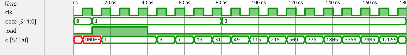
Notice that the number of
q[511:0]is display by decimal format.
HDLBits Simulation Waveform

Notice that the number of
qis display by hex format.