3-bit LFSR (HDLBits)
Linear Feedback Shift Register
📌 Question
Taken from 2015 midterm question 5. See also the first part of this question: mt2015_muxdff
my solution of mt2015_muxdff is here: DFF and Gates
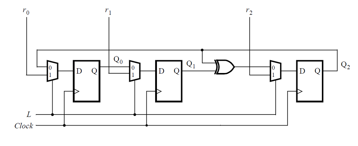
Write the Verilog code for this sequential circuit (Submodules are ok, but the top-level must be named top_module). Assume that you are going to implement the circuit on the DE1-SoC board. Connect the R inputs to the SW switches, connect Clock to KEY[0], and L to KEY[1]. Connect the Q outputs to the red lights LEDR.
🧑💻 Code Example
RTL Code
module top_module (
    input wire [2:0] SW,      // R
	input wire [1:0] KEY,     // L and clk
	output wire [2:0] LEDR);  // Q

    wire clk = KEY[0];
    wire L   = KEY[1];
    wire [2:0] R = SW;
    reg [2:0] Q;

    assign LEDR = Q;

    always @(posedge clk) begin
        if (L == 1'b1)
        Q <= R;
        else
        Q <= { (Q[1] ^ Q[2]), Q[0], Q[2] };
    end

endmodule
Testbench Code
`timescale 1ns/1ps

module tb_top_module;

    reg [2:0] SW;
    reg [1:0] KEY;
    wire [2:0] LEDR;

    top_module dut (
        .SW(SW),
        .KEY(KEY),
        .LEDR(LEDR)
    );

    initial begin
        KEY[0] = 0;
        forever #5 KEY[0] = ~KEY[0];
    end

    initial begin
        $dumpfile("tb_top_module.vcd");
        $dumpvars(0, tb_top_module);

        // Initialize
        KEY[1] = 0; // L
        SW = 3'b000;

        // Wait for a few clocks
        #20;

        // Load initial value (L=1)
        SW = 3'b001;
        KEY[1] = 1; // L = 1
        #10;
        KEY[1] = 0; // L = 0, start shifting

        // Observe shifting
        #100;

        // Load another value
        SW = 3'b101;
        KEY[1] = 1;
        #10;
        KEY[1] = 0;

        #100;
        $finish;
    end

    initial begin
        $monitor("Time=%0t L=%b SW=%b LEDR=%b", $time, KEY[1], SW, LEDR);
    end

endmodule
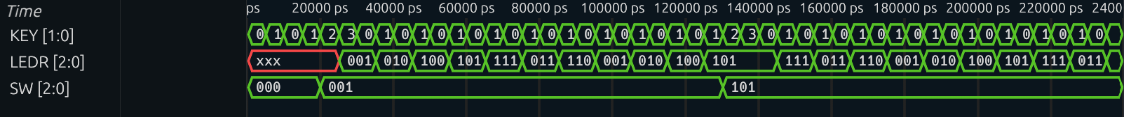
🔬 Results
Simulation Waveform
Synthesis RTL-level Schematic

Synthesis Gate-level Schematic
